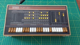
Here is my experience of building the Obsolescence Guaranteed PiDP-8 Kit.
I won't go over the entire process to build the kit, there's already a lot of information available on Oscars site and plenty of other people have done descriptions of their builds.
I will however detail some of the issues I had and any changes I made below:
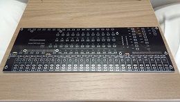
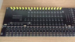
PCB and Soldering
-
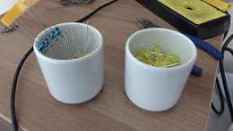
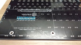
I used the chip holder to hold the LEDs in place when soldering - It was quite short (could only hold about 3 LEDs at a time)
but I just moved it along the row so the previous 2 LEDs were holding the next one in place.
-
I burnt the plastic of one switch with my soldering iron and another switch didn't work when tested. I got two replacement
switches from Oscar but the one I thought wasn't working started working, so I now have a spare :)
-
I noticed some of the screw and solder holes are visible behind the front panel so I masked them up with black tape.
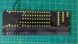
Spacewar Panel Test
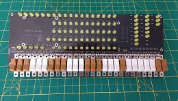
Mounting
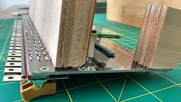
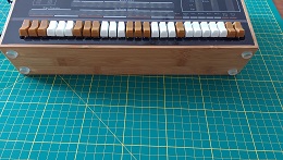
- I used the blocks in the way Oscar details. For the long block I tried to test fit the pcb and panel with the block
underneath - I went with 1mm overhang in the end (2mm would be too much). I figured I could also sand down the block (some
people were reporting it needed to be flush with the pcb with no overhang).
In the end I found the pcb refused to sit up against the right hand side of the case (even with all the screws holding the block) so I had to wedge
some folded paper in the left hand side to stop the pcb going over to the left.
- I also shaved of a corner of the long block using a plane so it would not touch the solder points and would sit flat (see photos)
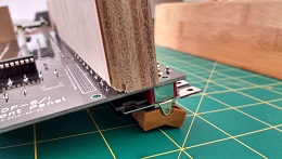
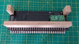
- With the two small blocks I tried to place them as Oscar had in the photo. One of the blocks was conflicting with the solder
points so I had to cut a chunk of the wood out to make it sit flat. It looks a little flimsy now but I don't think it will cause problems.
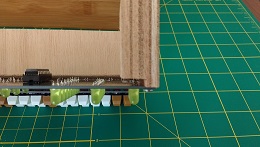
- Another problem people report is that the panel does not sit right because the bottom is sitting on top of the switch tags.
I decided to cut of some of the lip using some craft knifes.
Finishing touches
-
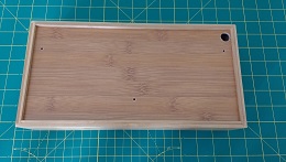
I also found the panel wouldn't fit very well without bending outwards, so I also had to shave some bamboo at the sides.
Where I had been struggling to fit it some of the panel markings came off around the edge.
Using some black paint on the panel I went over these and it made it look a lot better.
-
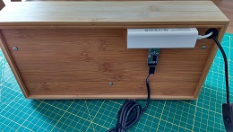
I made a hole in the top corner - this seemed the most sensible since the pi zero connectors are there and it was the shortest distance to them.
-
For the power cable I used a USB cable with an integrated switch. I thought having a USB connector made more sense
as it meant I could power it from pretty much anything with a USB port.
-
I decided to get one of the usb/ethernet hubs as Oscar had and mount on the back, this lights up blue when the pi is powered
meaning it doubles up as a discrete power light.
- I added some plastic feet on the bottom to stop it moving when the switches are used.
Serial port
- I wanted to be able to connect to the PiDP-8 but didn't want to rely on the wireless as being the only way.
Enabling the serial port seemed like a lot of hassle so I went with the USB serial ttl route as Oscar suggested.
Instead of 2 cables I ended up getting 1 cable plus another unit built into a stick with the pins on it.
This meant I could plug it into the hub and wire up the cable.
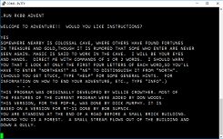
Here we are running "Adventure" in a terminal.
Conclusion
This is a great little project.
The soldering work is not difficult at all assuming you have some basic soldering skills.
There are a few places you might get caught out but as long as you read through Oscar's notes several times and plan ahead you shouldn't have any big issues.